Whats different about OSMA Underfloor Heating OSMA UFH products have been designed to provide the highest possible heating. The way I work it out is that at 200mm pipe centres a 100 meter roll will give you 20 m2 of area covered.

Understanding Zone Controls For Underfloor Heating Underfloor Heating Systems Underfloor Heating Hydronic Heating Systems
We should start to be able to see the heated wire through the tile at this point.

. Underfloor heating systems because of the lack of any device in the heated volume preferred by architects. It will look like an orange line in a serpentine pattern weaving back. This doesnt sound right for underfloor heating but im missing why the.
All components of the SCHÜTZ underfloor heating circuit manifold are optimally co-ordinated consistently following the system concept in combination with the manifold cabinets and can be used for underfloor heating and cooling systems. I have chosen to avoid hypothetical situations and to base my book on actual. LoopCAD is the premiere software for the fast creation of professional quality circuit layout drawings for radiant heating systems.
Heat is monitored and controlled by intelligent thermostats to maintain a consistent temperature throughout the property or individual zones. The maximum heat output for underfloor heating systems is 100 Wm 2 for concrete floors and 70 Wm 2 for timber suspended floors. People often ask me for central heating diagrams showing how the pipework circuits are arranged in a central heating system.
Turning your underfloor heating room thermostats down by just 1 degree could save around 80 and 330kg CO2 per year according to the Energy Savings Trust. The other two are. Let our heating experts help you get what you need for your project.
From what I can find out on their website such a length of cable will amount to 640w therefore requiring no more than 3A. Better controllability A bespoke design will consider how each room is used so that every space can be set at a different temperature and at different times for complete comfort. The first two are completely obsolete in domestic heating and only rarely encountered.
Calculate heat losses and amount of heat required for each room or zone. For hydronic underfloor radiant heating systems the systematic design process can be described as a 12 step program beginning with the heat loss and ending with the head loss. Step 1 - Heat Loss q Btuhr per zone.
Too many North-facing glass surface structures areas and especially heat loss in cold climate regions is more than the amount of heat must be given from the floor unit. For any underfloor heating system to work efficiently the property needs to be built to current building regulations and no rooms should lose more than the above. Diameter Less then 120 ft in length less if there is a Ubend The ductwork must be pitched to allow for condensate to drain eUblai reles materials it will need to last 40 years Natural Ventilation Typical problems Ductwork becomes plugged by debris or rodent nests.
This circuit was designed to control the underfloor heating pump independently or via the switch in the living room thermostat. LoopCAD Radiant Heating Software. The all-new LoopCAD 2021 offers advanced design features including integrated heating and cooling load calculations detailed hydronic calculations snowmelt design 3D.
In the section covering the circuits I felt it was desirable to highlight the numerical examples so that notes and observations of general interest could be drawn from them. Incorrect design can lead to a heating system that is under-specified meaning that the desired heat output in each area is not achieved. Flooring surface temperature of 29oC begins to disturb people in the room to be over.
There are almost infinite variations but there are four main types. Get the TIC ready and start scanning the floor. Let the system cook at 15 to 2 amps for about 10 minutes.
The underfloor heating temperature you choose can make a big difference to both the comfort of your home and your bank balance. You can set this using your underfloor heating control panel. Heat loss influences everything in the design process.
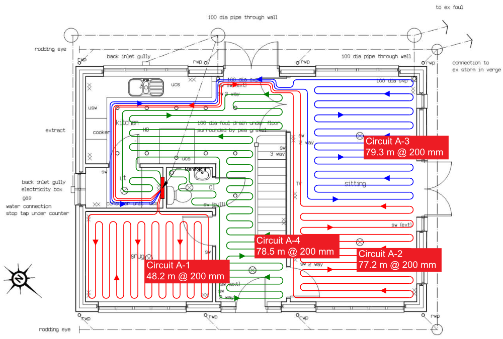
The design has been made very flexible and can be connected in four different ways. The design of an underfloor heating system in a new build is a straightforward process consisting of 6 main steps. Roughly 1 m2 of floor area is 5m pipe.
Calculate number of circuits required. If you have a combined Flow and Return piping to the manifold of 10m then you will have enough pipe left to cover 18m2 of floor area. 333 Design criterias 15 4 CASE STUDY ON PUMPS 17 41 Task 17 42 Results 19 5 CASE STUDY OF USING FLOW CONTROL 24 51 Description of the circuit using heating batteries 24 511 The present solution of the heating circuit 24 512 A system using the traditional shunt group 26 513 A flow control system without valves with just the pump 27.
Design advice Ductwork should be at least 8 in. Relating to the choice and design of the. The design and installation of underfloor heating using OSMA UFH components available through Merchant Stockists.
We can help you through every step of the process. Call now and save. You can use it to create and layout a room with the exact measurements and the fixtures of your choice in order to ensure that your quote is as accurate as possible because you can use the.
The underfloor heating design process includes detailed tube layout and electrical drawings giving an easy to follow plan that makes installation simple. Rectifying mistakes caused by design error after the installation has taken place will. The underfloor heating design process includes detailed tube layout and electrical drawings giving an easy to follow plan that makes installation simple.
Underfloor heating works by distributing a lower temperature of warm water through a circuit of pipes beneath the finished floor. Determine water flow temperature and pipe spacing. Ive taken a look at a consumer unit today and noticed that the previous electrician wired bathroom underfloor heating using a 20A circuit breaker.
These products are primarily designed for use in new-build residential applications up to four circuits. The compact dimensions and the vertically offset arrangement of the inflow and return of the individual heating circuits results in the low. Proper underfloor heating system design is essential to make sure that the system being installed is sufficient for the area that is being heated.
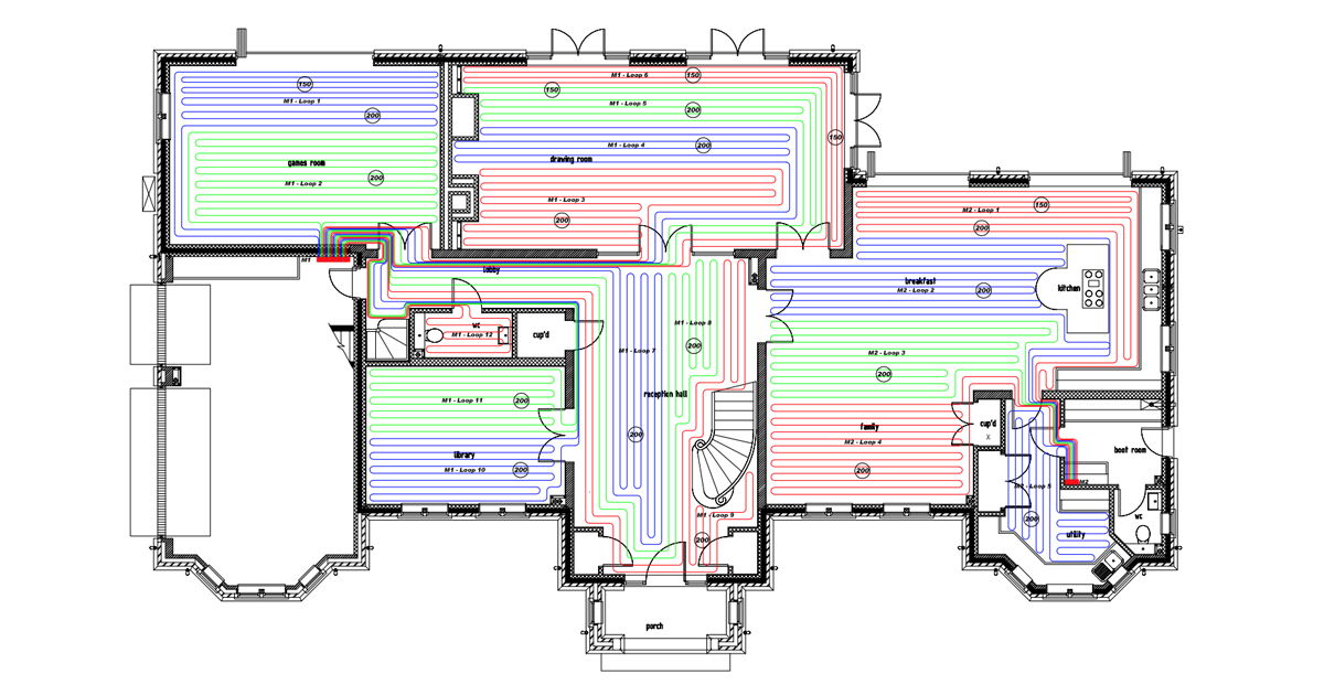
Underfloor heating pipe should be laid at 200mm centres dependent upon design. This topic is part of our P rofessional Development curriculum. 1 The temperature sensor 1 is connected to the inlet pipe of the underfloor heating a Temperature sensor 2 is shorted.
Relating to heating circuits and heat emitters. Standard Design Under Floor Heating Uf Heat Exchangers UFH Circuit Return UFH Circuit Flow Installation Notes - Pipe laid in floor at 200mm centres. Ad Heat a single room or an entire house.
All components of the SCHÜTZ underfloor heating circuit manifold are optimally co-ordinated consistently following the system concept in combination with the manifold cabinets and can.

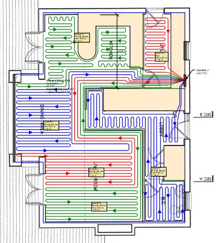
The Plan Of The Building Underfloor Heating Loops And Location Of Download Scientific Diagram
Underfloor Heating Design A Comprehensive Guide

Underfloor Heating Pipework Layouts Underfloor Parts
Rojasfrf Underfloor Heating
Priority Cad Design Service The Floor Heating Warehouse
Underfloor Heating Pipe Layout Underfloor Heating Systems Ltd

Free Cad Design Underfloor H Design

Attention To Detail Is Everything Optimum Underfloor Heating
0 komentar
Posting Komentar